
Pioneer is a leading car stereo manufacturer. If you have upgraded your factory car stereo with an aftermarket Pioneer stereo and wondering how to wire it, then you have visited the right page. In this article, we will guide you through the Pioneer wiring harness color code. We have included the color code Pioneer car stereo wiring diagram to make it easier for you when wiring. You can also check the Pioneer AVH 120BT wiring harness color code.
Double Din Pioneer Wiring Harness Color Code
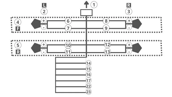
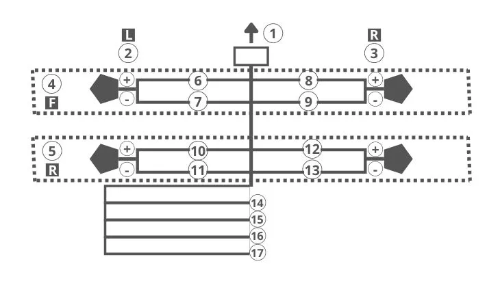
If you have a double din Pioneer car stereo, such as the Pioneer FH-X720BT, here is the wiring diagram to use when connecting the front and rear car speakers:
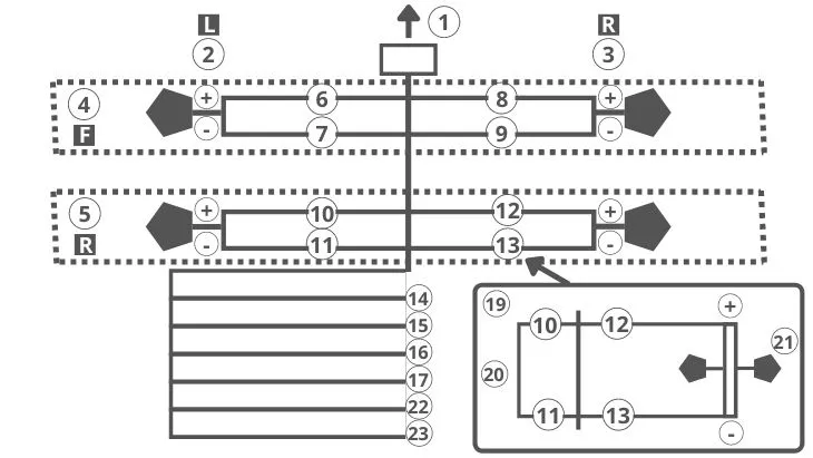
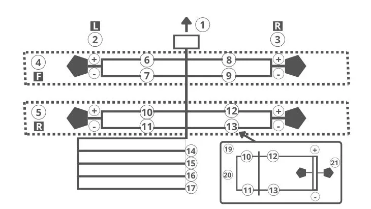
If you have a double din Pioneer car stereo, here is the wiring diagram to use when connecting it to front speakers and a car subwoofer:
Here’re the explanations of the color codes when wiring Pioneer harness to front and rear speakers, and to front speakers and subwoofer using the above diagrams:
1- Connects to the power cable.
2- Connects to the left channel speakers.
3- Connects to the right channel speakers.
4- Connects to the front left speaker.
5- Connects to the front right speakers.
6- Represents the white wire on the harness.
7- Represents the white/black wire on the harness.
8- Represents the gray wire on the harness.
9- Represents the gray/black wire on the harness.
10- Represents the green wire on the harness.
11- Represents the green/black wire on the harness.
12- Represents the violet wire on the harness.
13- Represents the violet/black wire on the harness.
14- It is the black wire on the harness that connects to the grounding point, preferable to a paint-free metallic part of the chassis.
15- It is the yellow wire on the harness that connects to a 12 volts constant power supply terminal.
16- It is the red wire on the harness that connects to a 12 volts power supply terminal, which is controlled by the car ignition switch.
17- The blue/white wire on the harness that connects to the antenna or amplifier control terminal.
18- Represents how to connect to a single 4-ohm subwoofer.
19- Represents how to connect to a 2-ohm subwoofer. In this case, don’t hook the green/black wire. Only hook the subwoofer to the violet wire and the violet/black wire.
20- You won’t use the green and green/black wires.
21- Shows how you connect two 4-ohm subwoofers.
22- It is the orange/white wire that connects to the illumination wire of the car.
23- The yellow/black wire is only used with a Pioneer FH-X520UI double din CD receiver.
Pioneer Car Stereo Inputs/Outputs
Here is a diagram representing the inputs/outputs on Pioneer FH-X720BT double din car stereo:
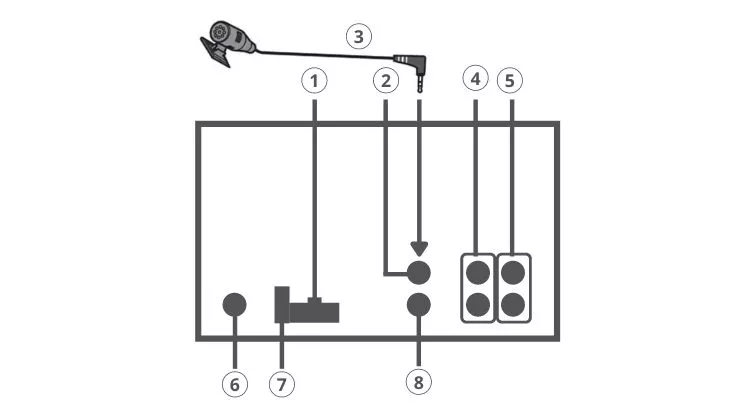
1- Input for the power cable.
2- Input for a microphone.
3- Input for an external microphone.
4- For subwoofer output or rear output.
5- For front output.
6- For antenna input.
7- The fuse goes here.
8- Input for wired remote control.
Single Din Radio Pioneer Wiring Harness Color Code
If you have a double din Pioneer car stereo, such as the Pioneer MVH-290BT, here is the wiring diagram to use when connecting it to the front and rear speakers:
Here’s a wiring diagram for connecting a Pioneer single din stereo to a sub without an extra amp:
The Pioneer wiring harness color codes for the above wiring diagrams, including for a 16-pin pioneer wiring harness color code, are as follows:
1- You hook it to the power cable input.
2- Represents the left channel connections.
3- Represents the right channel connections.
4- Shows the connections for the front, left channel speaker.
5- Shows the connections for the rear, left channel speaker.
6- Represents the white wire on the harness.
7- Represents the white/black wire on the harness.
8- Represents the gray wire on the harness.
9- Represents the gray/black wire on the harness.
10- Represents the green wire on the harness.
11- Represents the green/black wire on the harness.
12- Represents the violet wire on the harness.
13- Represents the violet/black wire on the harness.
14- Represents the black wire on the harness, which is the grounding wire that you connect to the chassis.
15- Represents the yellow wire on the harness, which you connect to the 12 volts constant power supply.
16- Represents the red wire on the harness, which you connect to the 12 volts power supply on the ignition switch.
17- Represents the blue/white wire on the harness, which you connect to the antenna or amp control terminal.
18- Shows how you connect a single 4-ohm subwoofer.
19- Shows how you connect a single 2-ohm subwoofer. In this case, you will hook the subwoofer to the violet and the violet/black wires. However, don’t hook the green and green/black wires to any component.
20- You won’t use these wires.
21- Shows you how to connect two 4-ohm subwoofers to the stereo.
Here’s a wiring diagram for connecting a Pioneer single din stereo to an amplifier:
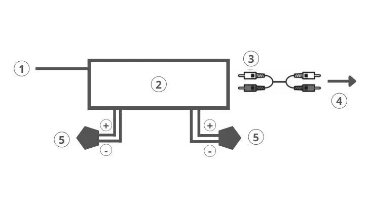
1- Connect this wire to the remote control.
2- Shows where you connect to the blue/white wire on the harness.
3- Connects the RCA output on the receiver to the amp.
4- Connects to the RCA input on the amp.
5- Connects to the subwoofer and/or rear speaker.
Final Thoughts
Although the majority of Pioneer car stereos use a similar wiring diagram, it is advisable to check the manual of your specific stereo model to ensure you’re doing the right thing. Hopefully, we have helped you with wiring your new Pioneer car stereo with simple instructions and wiring diagrams. As you can see, it is something you can do by yourself rather than hiring a technician and saving some money.
Frequently Asked Questions
What color is a wiring harness?
It is important to understand the color code for the aftermarket car stereo wiring harnesses. Failure to connect the harness properly can damage your car stereo and the attached components. The standard color code for a wiring harness is as follows:
Black- Grounding.
Yellow- 12 volts constant power.
Red- 12 volts accessory/switch.
Blue- For antenna remote.
Blue/white- For amp remote turn on.
Green- Rear left speaker, positive terminal.
Green/black- Rear left speaker, negative terminal.
White- Front left speaker, positive terminal.
White/black- Front left speaker, negative terminal.
Gray- Front right speaker, positive terminal.
Gray/black- Front right speaker, negative terminal.
Purple- Rear right speaker, positive terminal.
Purple/black- Rear right speaker, negative terminal.
Orange/white- Illumination or dash light dimmer.
How do you wire a Pioneer stereo?
In this guide, we have provided detailed information on how to wire a Pioneer stereo. Read through the above wiring diagrams and Pioneer wiring harness color codes for details.
What color represents the power wire on a Pioneer car stereo?
You connect to power via the red and yellow wires. Yellow is connected to 12 volts constant power while red is connected to 12 volts accessory/ignition switch.
Which color wires in a stereo wiring harness go together?
Green and green/black go together for the rear left speakers. Purple and purple/black go together for the rear right speakers. Gray and gray/black go together for the front right speakers. White and white/ black go together for the front left speakers. Just ensure you get the polarities right.
What is the orange wire on a Pioneer radio harness?
The orange wire connects to the display illumination dimming/dash lights.
What is the black wire on a Pioneer radio harness?
The black wire is for grounding the radio to the chassis.
Michael Evanchuk is a San Francisco-based sound engineer with 20 years’ experience installing, troubleshooting, and repairing commercial, automotive, and household sound equipment. Evanchuk owns an auto stereo center, where he offers highly competitive car audio installation and repair services. He has written dozens of articles on different sound engineering topics, all of which have been published in leading journals, blogs, and websites.


