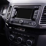
Today, it is almost impossible to find a car without a touchscreen. One advantage of having a touchscreen in your vehicle is the simplified operation while allowing you to keep your eyes on the road.
The Pioneer AVH-120BT offers simple yet compelling features designed to enhance your in-car entertainment. It lets you access features such as Bluetooth for audio streaming and hands-free operation.
However, if your car has a small dash opening, fitting a conventional receiver might seem impossible. But Pioneer’s AVH-120BT can help solve this problem, thanks to its compact 6.2″ touchscreen display. The multi-media receiver is built into a slender chassis, making it easy to install in spaces that other units don’t fit.
But how do you go about installing the media receiver in the car? Doing the wiring yourself can be somewhat overwhelming, so it is crucial you do a bit of research and approach the process with patience. And since every car is different you may want to get accustomed to your specific model before you get started.
Wiring Pioneer AVH-120BT
Get a wiring adaptor
Once you unbox your receiver, the first thing you’ll need to get is the wiring harness adaptor. You can purchase one online, but you can also get one at local auto-parts or electronic stores. An adaptor provides a safe way to connect each wire to the adaptor, which helps reduce wiring mistakes.
Identifying and connecting wires
If using a wiring adaptor is not possible, then you’ll need to carefully determine the function of each wire, and where they need to be connected. Examine each wire at a time and connect each to the corresponding wire on the car stereo. Ideally, this receiver will need the following connections;
- Yellow wire -12 volt wire for terminal supplied with power
- Red wire- serves as the power wire that connects to the red wire of the car
- Black wire- this wire serves as the ground wire, and it needs to correspond with the ground wire from the car
- Orange/white- connects to lighting terminal
- Blue/white-connect to the power amp
- Violet/white- connects to the rear lamp. This connection is used to alert the driver whether the car is moving forward or reversing.
- Light green- connects to the brake switch to track the status of the parking brakes.
- The rest of the wires are for speakers, the subwoofer, parking camera, rear/front lights, and other audio components that you may need to connect to your receiver. Ensure to match each wire with the appropriate cable from the car.
Pioneer AVH-120BT Wiring Diagram
Secure all wires
Once you’re sure that all wires are connected to their corresponding cables, you may want to find ways of securing your connections. The idea is to ensure that there is no bare wire that is left exposed. Insulating your wires will help protect you and those around you from the risk of electric shock and electric fires. The simplest way is by wrapping the wires together using electric tape to bond them together. Another method involves melting a soldering agent onto the wires, and as the solder solidifies, it will make them stick together.
Tips and Warnings
Do not install this receiver where;
- The wires might obstruct your vision or interfere with your ability to drive or,
- The wiring might interfere with the normal functioning of car safety systems such as safety airbags.
- Avoid connecting the yellow wire directly to the car’s battery. By doing so, any vibration might result in short-circuiting, leading to significant damage.
- Ensure that you don’t route wires where they are exposed to very high temperatures or humidity. If the leads become heated, the insulation might wear off, resulting in malfunctioning or permanent damage. As such, ensure to avoid areas close to the heater, air conditioner, or places that they can be exposed to direct sunlight or rain.
- Wrap any loose cables to ensure that they don’t injure the driver or other passengers if the car stops abruptly.
- Avoid cutting or shortening the wires. By doing so, the leads may fail to work as expected.
- Lastly, test the wiring to ensure that everything is connected properly before making the final installation.
You may also read: Simplified Power Acoustik RZR1 2500D Wiring Diagram
Michael Evanchuk is a San Francisco-based sound engineer with 20 years’ experience installing, troubleshooting, and repairing commercial, automotive, and household sound equipment. Evanchuk owns an auto stereo center, where he offers highly competitive car audio installation and repair services. He has written dozens of articles on different sound engineering topics, all of which have been published in leading journals, blogs, and websites.


